|
Atmospheric Pressure (760 Torr) to 100 Torr
You need a vacuum gauge that works at one atmosphere an shows whether
your vacuum pump is working. These are usually based on a bourdon
tube with a flexible metal chamber or finger that changes dimension
when there is a pressure change. The chamber is mechanically connected
to a mechanical or electronic meter face to show the pressure. All
you need is a crude instrument with limited accuracy because gauges
that work in the interesting range for plasmas often do not work
well at one atmosphere.
If you are using an automotive A/C repair manifold
you will get two gauges a red gauge with a -30 to 120 psi range
and a blue gauge that measures pressure above one atmosphere 0 to
500 psi (blue). These are pretty much useless because you will be
working in the -29.9 to -30 psi range and 0 to -30 is only 20o
movement on the red gauge. If you want to watch the pumpdown you
will need is a gauge that goes 270o
from one atmosphere to -30 psi.
I bought an automotive vacuum gauge ($35) for chamber
testing that covers the pump down range. For most experiments the
red gauge is good enough to tell me whether the pump is working
and the valves are set right and I do not bother the drill a port
into my vacuum chamber for a gauge to just measure the pump down.
Plasma Range 10 Torr to 10 milliTorr
Most of the gauges in this range are based on the
ability of the gas molecules to remove energy from an electrically
heated wire. In a hard vacuum the wire can only lose heat by radiation
and with a small surface area the wire has to be very hot to lose
much heat at all. The wire is chosen with a resistance that is has
a high temperature coefficient.
If a constant voltage is placed across the wire it
will remain at a low temperature and low resistance at one atmosphere
but its temperature and resistance will rise quickly as the pressure
approaches a hard vacuum. The effect is even more dramatic if a
constant current is used but the electronics are more complicated.
The best known gauge using this effect was invented
in 1906 by Marcello Pirani and most heated wire gauges are called
"Pirani gauges". The basic technology has changed little in a hundred
years and most of the advances have been in making a gauge that
can be mass manufactured (less variation from unit to unit) and
holds its calibration (is not affected by age or physical abuse).
You can buy a quality Pirani gauge for about $300
but you really need the $2000 meter to make sure you get the accuracy
and more important so you do not stress the fine heated wire and
burn it out. For the poor starving inventor this is a little pricey
so like most of this site I am going to show you how to build your
own for a couple of bucks.
Light bulbs have tungsten wires that have a resistance
with a high temperature coefficient. If you punch a hole in an ordinary
light bulb you have a Priani gauge. The problem becomes one of choosing
a light bulb with the right properties, building the electronics
to apply a constant current, and calibrating the gauge.
Finding the Right Light Bulb for Your Pirani
Gauge
An ordinary 100 watt bulb could be used as a Pirani
gauge but it is too big, too fragile and would consume too much
power. You want a small, low wattage bulb with a glass shell that
will hold up after you drill a hole in it. Flashlight bulbs are
small and durable but it turns out their resistance is too low.
What you need is something the size of a flashlight bulb but uses
much less current. This means you are looking at decorative lights,
Christmas tree lights and industrial panel lights.
Your choice is limited by the fact that most small
operational amplifier chips have a 50 ma maximum current and 20
volts maximum voltage. A light bulb has its highest resistance in
a vacuum and lowest resistance when cold. Most light bulbs are sealed
with 10 milliTorr argon gas so a measure of the cold resistance
and the voltage/current rating of the bulb is a good place to start.
A 12 volt 0.78 watt (65 ma) bulb like the IKEA E512V
has a hot vacuum resistance of 12/.065 = 180 ohms. The measured
cold resistance is 20 ohms which makes it an good candidate with
a 9:1 resistance ratio. A 48 volt 38 ma telephone office panel bulb
has a 48/.038 = 1200 ohm hot resistance and a measured cold resistance
of 96 ohms giving it a 13:1 ratio. In a Pirani circuit you get about
half the hot/cold ratios (about 5:1) so both of these are good choices.
The operating range of our opamps is a critical factor.
An 8D 12 volt lantern bulb that needs 500 ma for a hot resistance
of 24 ohms and has a measured cold resistance of 1.4 ohms which
is a very nice 17:1 ratio but it would a lot of current to drive
the circuit. A 7 watt (7/120 = 58 ma) night light has a hot resistance
of 120/.058 = 2070 ohms and a measured cold resistance of 192 ohms
giving it a 11:1 ratio but it would need a lot of voltage to drive
the circuit. In fact over a 0 to 12 volt range the 7 watt nightlight
only has 1.4:1 ratio because you cannot get the filament hot enough
to get the Pirani effect.
A simple rule of thumb is you will be operating your
gauge at roughly one third the rated voltage and current for the
bulb. For the IKEA bulb this would be 4 volts and 20 ma and the
telco bulb would be 16 volts and 12 ma. Both are in the opamp range.
Compare this to the lantern bulb (4 volts and 170 ma) and night
light (40 volts and 19 ma) both which fall outside the range of
our opamps. Christmas tree bulbs come 50 on a 120 volt string so
operating them at one third of their 120/50 = 2.4 volt rating would
mean 0.8 volts which is probably too low.
Turning your Light Bulb into a Pirani Gauge
Sensor
To turn a light bulb into a Pirani gauge you have
to drill a hole in the glass shell. Grinding or drilling the bulb
is often causes the glass to shatter. If you just heat the glass
it will form a dimple that will collapse into the bulb.
The simplest way to heat a wire white hot and push
it into the glass to melt a hole. I use a stainless steel turkey
lacer ($1 for 6) and heat it with a propane torch. After destroying
a few bulbs I was able to make a fairly neat 1 mm hole in the glass
shell. The result is an extremely durable sensor that can be soldered
or screwed into a mount.
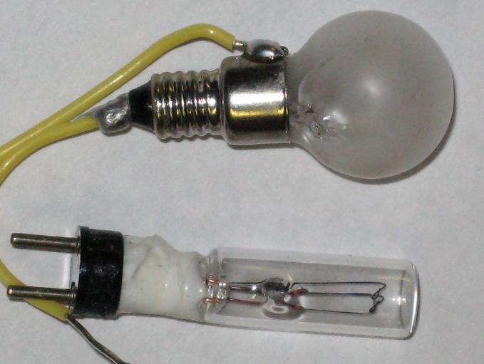
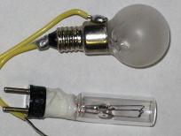
You can just make out the holes in the shells of the
IKEA bulb (on the top) and the telco bulb (on the bottom) in the
following picture:
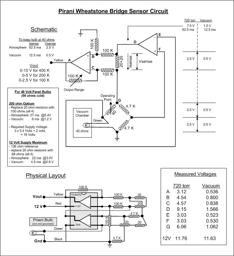
Building a Pirani Sensor Circuit
You can use a constant current or a constant voltage
but the most sensitive circuit uses a Wheatstone Bridge to maintain
a constant resistance and the measures the current on the bridge
to provide a sensor value. The circuit I designed has the advantage
that one end of the Pirani bulb is grounded making it easier to
install in the vacuum chamber.

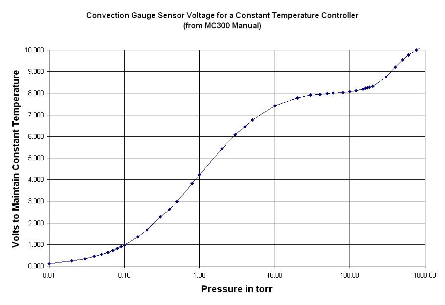
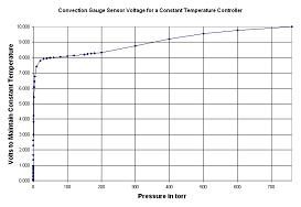
Pirani Gauge Calibration Curve
The sensor and circuit give the most sensitive measure
of pressure but he Pirani curve is highly non-linear. In fact even
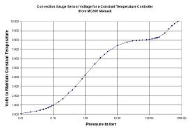
on a log plot the curve is still highly non-linear. To appreciate
the technology it is a good time to look at some commercial
documentation and actual commercial product graphs. The first
is a standard plot of voltage against log of pressure:
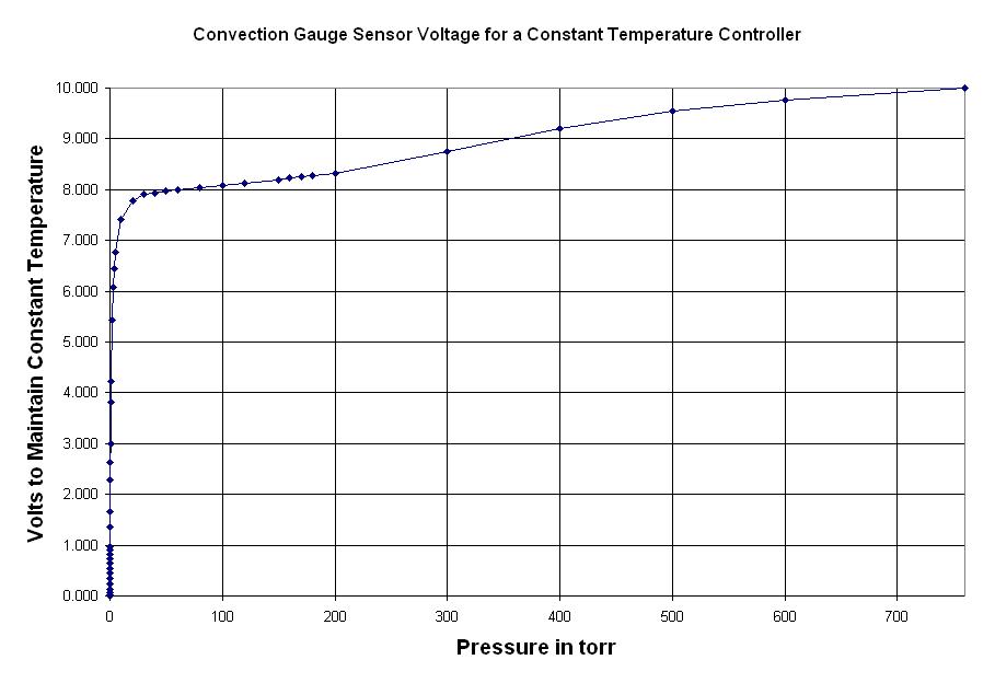
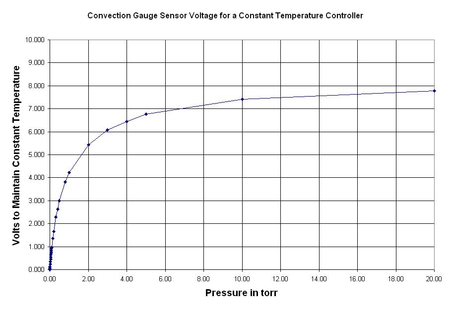
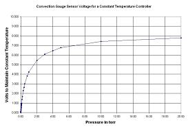
The non-linear nature of the sensor is even more apparent
in when pressure is plotted on a linear scale:
Expanding our experimental region from 1 to 20 torr
we still have a lot of non-linearity but there is enough voltage
change to create a reasonable calibration chart:
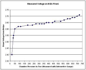
An actual measurement of a IKEA sensor with my bridge
circuit using the automotive pressure gauge as a standard from one
atmosphere to 50 torr:
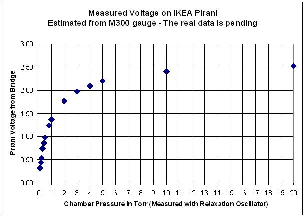
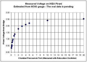
Using the relaxation oscillator circuit described
at the bottom of the gases page the curve below 50 torr is:
With these curves I was able to spline fit and create
a table I use for measuring the gas pressure in all subsequent experiments.
|