|
"Inventor Found Electrocuted in Basement
Lab"
"Sunday morning a family member found a inventor who was working
on plasma physics slumped over a desk electrocuted by the experiment
in progress. The coroner said that the death had occurred several
hours earlier and the inventor had been working alone so there was
little chance of anyone arriving in time to prevent the tragedy."
I find posting my obituary above my desk helps to
make me aware of the hazards working with high voltage. I also put
warning signs on my equipment as a continuous reminder not to do
something stupid.
If you stick your hand in the back of a TV set you
will get a shock that will tighten every muscle in your body by
it will probably not kill you. It is 20,000 volts but there is not
enough current to finish the job. If you do your own house wiring
and accidentally touch the wrong bit of metal it will probably not
kill you because it is probably not across your heart and the 120
volt house current (180 volts peak) is not enough to overcome dry
skin resistance and deliver a lethal current.
The power supply designs shown here are in that "sweet
spot" with enough voltage to overcome dry skin resistance and
enough current to kill you. If you have not suffered at least a
dozen electrical shocks you should probably stop right here and
take up a safer hobby like sky diving.
A technical note on high voltages. 50 ma on a path
that crosses your heart (like hand to hand or right hand to left
foot) will kill most humans. All you need is 200 volts to overcome
your skin resistance and you will get that 50 ma easily. These power
supplies will kill you quick if you are not extremely careful.
You can either wear plastic gloves (not fabric -
it has holes) or use the "one hand rule" and put one hand in your
back pocket whenever the power is on. You put one hand in your back
pocket so if something falls over you will not be tempted to grab
it with both hands. In any case you will be slow, clumsy or one
handed whenever you are working with the power on. Take your time
- do not rush - better clumsy than dead.
Float Ground Power Supplies
Normal commercial power supplies are carefully grounded
to the third pin on the power cord. This is to ensure a short in
the supply will not lead to house power on the case. The problem
with high voltage supplies is that means every grounded metal object
is a return path for a lethal voltage. I want to know where my high
voltage points are so a floating ground means there are only two
ends to keep track of. I use a lot of plastic around my high voltage
components to make sure the problem solved by the third pin ground
is extremely unlikely in my designs.
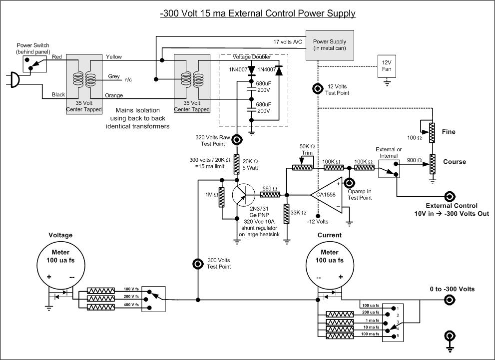
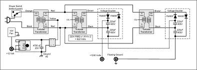
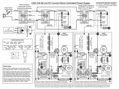
The simplest way to get isolation and a floating ground
is to use two identical transformers wired back to back. This gives
you 120 volts AC from the second transformer and with a doubler
you get 340 volts DC with a floating ground (120 x 1.414 x 2). In
my case I needed a negative supply with a 0-10 volt programming
voltage I could drive from a computer.
The current was small enough I could use a shunt
regulator. This design means with an output of 0 volts DC the load
resistor must drop all 340 volts which is really wasteful. The design
however is safer than a series regulator because if you try to ground
the 340 volts through your body the maximum current is limited to
15 ma. I use this for new experiments where I am likely to be so
focused on the problem I might do something stupid. . . twice actually
and I'm still here. When I have stabilized the experiment I use a
less safe but more efficient power supply.

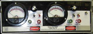
Ancient Analogue Meters?
There are two good reasons to use these old analogue
meters for high voltage supplies. If you put back-to-back diodes
across the meter posts an accidental high voltage short during construction
and testing will not destroy the meter (might kill you but the meter
will be okay). Put 300 volts on a digital panel meter and its bye-bye
$30. Do it a couple of times and you will switch to analogue meters.
The other reason is that the analogue movement makes
it easier to see how much trouble you could be in. I use a digital
watches and clocks but where the reading is both a value and a warning
I like analogue meters. Since speedometers in cars are still analogue
most people would agree with me.
Transformer Math
Many transformers have 120 volt AC and 240 volt
AC primaries. If you use the 120 volt winding on the input transformer
and the 240 volt winding on the output transformer you get a full
wave doubling. If you put a voltage double on the output you get
680 volts (120 x 2 x 2 x 1.414).
The advantage of connecting the low voltage secondaries
together (in the circuit above 35 volts to 35 volts) is wire size
on the primary and secondary are probable engineered to be the "right"
size for the ratio of currents they are designed to carry. Connecting
them back to back takes advantage of that engineering.
You could connect the 35 volt windings from the
input transformer to one half (17 volt winding) on the output transformer.
It would get double the output but that would put an excessive current
load on the 35 volt windings.
A better way is to try to match the impedance of
the low voltage windings better and use two output transformers.
Below is a example using dual output transformers and their 240
volt windings. This was not used because there are no cheap 1500
voltage transistors to create a variable supply.
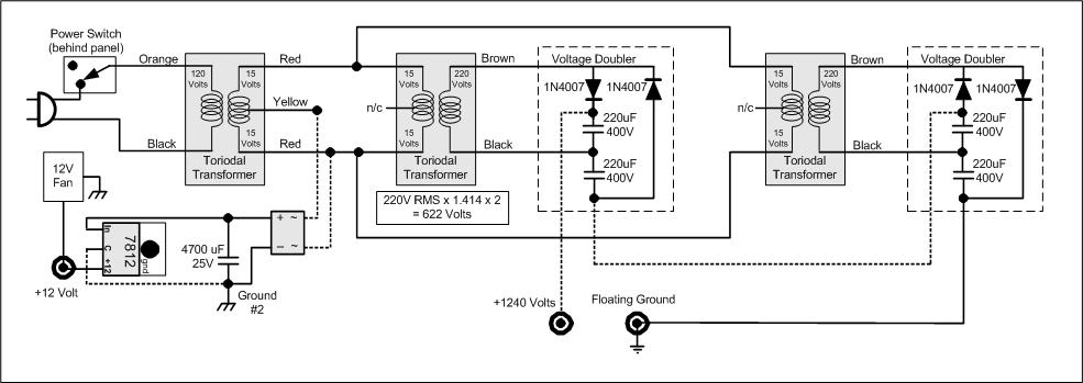
One last way to double the output voltage at the
transformer is to use four transformers. The two input transformers
are connected by their low voltage secondary winding to the two
output transformers. By joining the primaries of the output transformers
you get an isolated doubled voltage without sacrificing the engineering
margins on the transformers. Needs are lot of iron to make it work
so you'll have to get the transformers cheap (free) to make the
effort worthwhile.
Diode Doubler Math
You can also double the voltage by building out the
diode capacitor change to higher multiples. The problem is every
section of the chain gets fewer and fewer AC pulses and so ripple
becomes a major problem if you try to draw any amount of current
from the circuit. The circuit is called a Cockcroft Walton Multiplier.
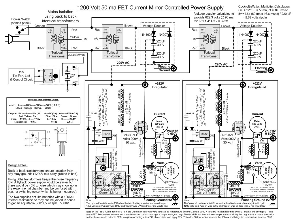
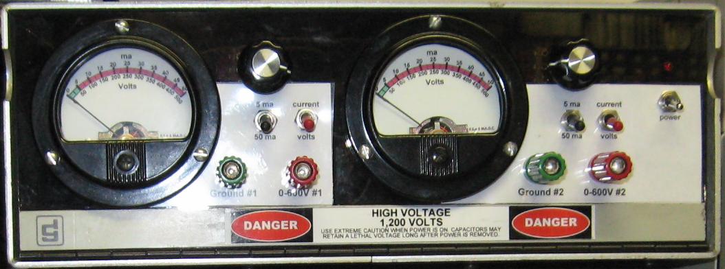
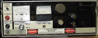
1200 Volt Variable Power Supply
The power supply design used for powering most of
the experiments is two variable 600 volt supplies that can be chained
together like a couple of batteries. This supply was difficult to
build because the extra safety circuitry apparently cased oscillation
in the high voltage FET transistors. Most of the safety circuitry
was stripped away and the power supply was eventually made stable
at all output voltages.
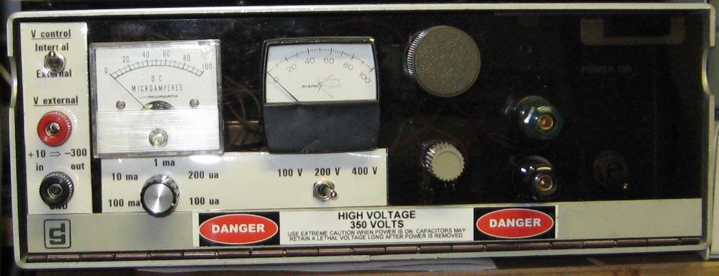
The front panel has a separate meter for each side
of the power supply so you have to add the meter readings to get
the output voltage. Connecting the left hand red jack to the right
hand green jack yields 1200 volts across the outer green and red
jacks.
|