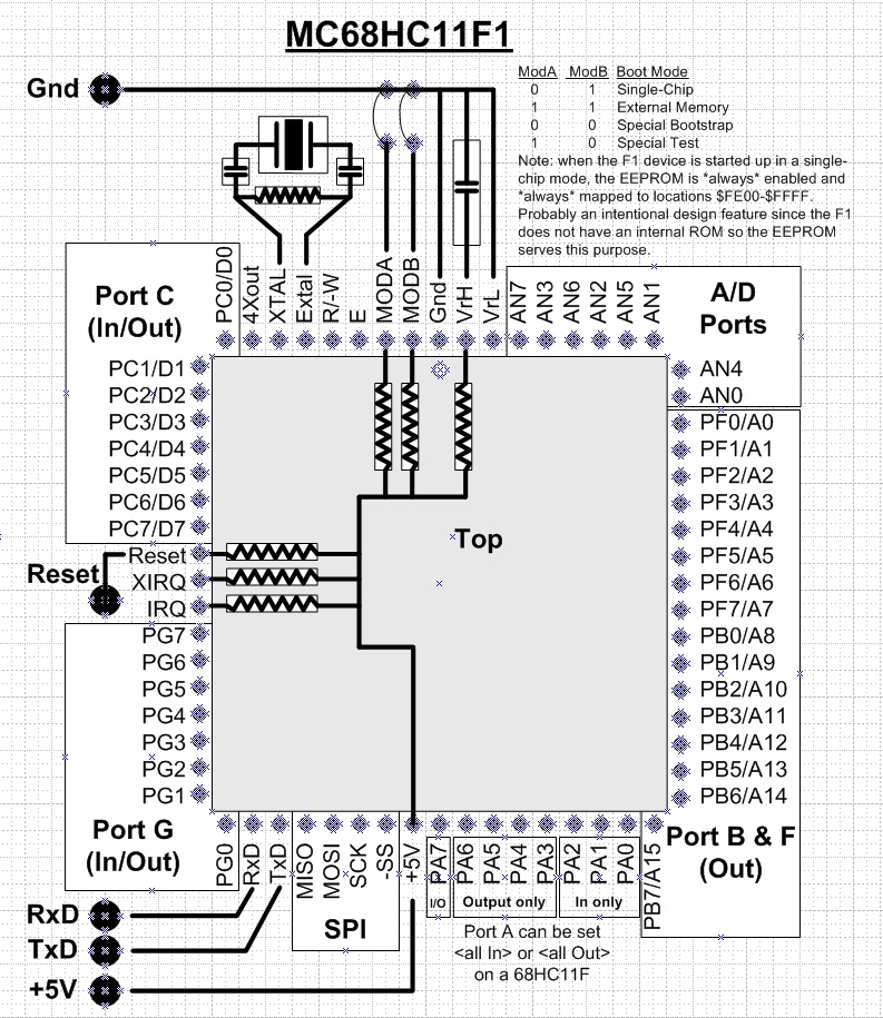
MODAMODBBoot Behaviour
High High Expanded
Low High Single Chip
High Low Special Test
Low Low Special Bootstrap
"Expanded" mode is the normal startup for a single board computer.
Port F is A0...A7, Port B is A8...A15, and Port C is Data0...Data7.
The default configuration expects 8KB of external RAM starting at $8000
and 8KB of external PROM starting at $C000.
We are not interested in this mode.
"Special Test" is some kind of access used by Motorola during factory quality control.
We are not interested in this mode.
"Single Chip" will be the permanent startup mode used when we are finished. The chip
starts at first EEPROM location ($FE00) and that is where we will install our "Talker".
This means a chip in a remote location (like inside a vacuum chamber) can be restarted
into a known state with a power fail.
The "talker" allows us to load programs into the 1024 byte RAM starting at $0000. These would
be used for special tasks like turning on/off port bits and taking A/D measurements in a specific
sequence. A local program would be much faster than reading and writing individual registers remotely from the
host PC via the RxTx (SCI). If the RAM program stalled or refused to relinquish control back to the
"talker" the chip can be power fail restarted putting the EEPROM back in control.
The talker needs a little RAM to operate so we put its stack at the end of the RAM ($03FF). When the
RAM based program is running it can safely use all 1024 bytes. When it finishes it would normally "branch"
to $FFE0 reinitializing the talker so there is no conflict. Whatever is running assumes
all of RAM is free for its use. If the RAM program needed to "return" to some specific state in the EEPROM
talker then it must not alter the top 9 bytes of the stack where the return state is stored.
"Special Bootstrap" is the mode used to install the EEPROM talker. When started in this mode the chip
maps a special ROM into visible memory. This ROM send out a "break" on the RxTx (SCI) looks for a "break" in return.
If it sees one it goes through an autobaud sequence and sets the discovered baud rate. It then downloads a program
into RAM and starts that program at $0000.
The downloaded program can be anything. In a teaching environment
it is a class assignment in 68HC11 programming. If the 68HC11 is on a
board with flash EPROM it is the program to load something as large as a Basic11
interpreter (8Kbytes) or a Buffalo monitor (8Kbytes). In an industrial or automative
setting it is a firmware upgrade. In an interactive development environment (IDE) it is a "talker" designed to
work with an IDE Client on a PC.
In our case it is the RAM talker is the one that comes with the JBug11 client. What it
loads is Dean's Special Talker (TalkJF1) into EEPROM.
Hardware Setup
You need to connect the Rx Tx ports on a 68HC11 to your PC.
In the past you'd use a COM port but modern PCs don't have them. You could find an old 32bit PC running any version
of Windows (all the tools will work) but you will have to provide an RS232 to RxTx adapter. The adapter takes the 0V...5V signals
off the RxTx ports and converts them to the -9V...+9V RS232 signal levels. You cannot just "level shift" because
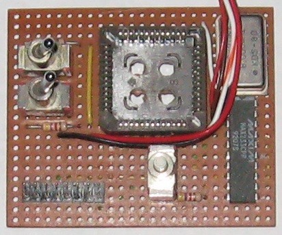
the RS232 signals are inverted from their RxTx source. You can make you own adapter using a MAX233 chip
(needs no capacitors):
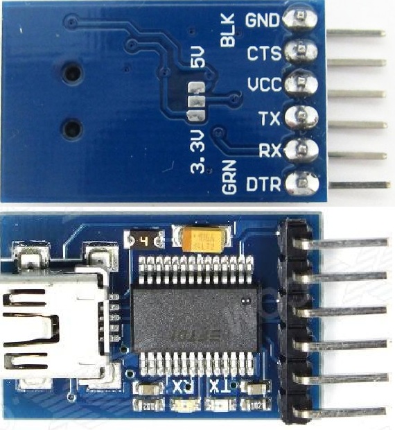
The simpler solution is to stay with a modern 64 bit PC and use current microcontroller development tools. For this you need
a USB to RxTx that can send and read a "break" character (not all do). The FT232RL from dx.com ($5.70) does and connecting
to the chip is relatively easy.
Once you have the talker loaded into the 68HC11 EEPROM you no longer need a "break" character so any USB to RxTx will work
fine. They will also work on a 32 bit PC so you can continue to load and test on the old PC.
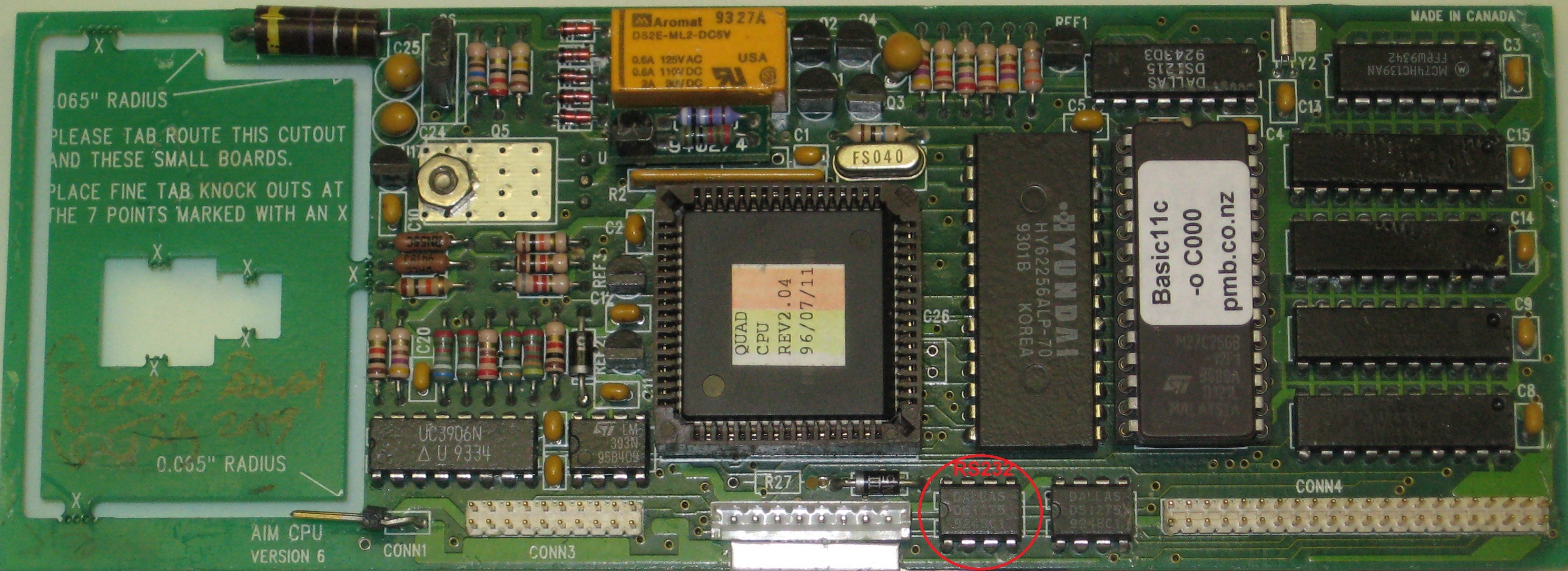
If your 68HC11F1 is on a board the RS232 may already be connected:
Now you have to add a crystal and a few other jumpers then connect power, ground, MODA, MODB, Rx, and Tx:
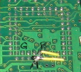
If your 68HC11F1 is in a socket on a board you leave it there and ground MODA (permanently) then use a shorting wire on MODB
to switch between modes.
When you are loading the talker into EEPROM twist the two wires together (A=B=gnd). In service A=gnd and B is floating:
If you managed to get the chip powered and connected (I always get Rx <--> Tx wrong ... it's like plugging
in a USB flash drive...always upside down the first attempt) you are now ready to load the talker into the EEPROM. Proceed
to loading the talker.